This is the process I used to install my turbo timer.  It works for me.
Follow these directions at your discression.  There may be steps
missing from these directions.  I assume no responsibility for any
problems/failures/malfunctions you encounter if you choose to follow
these directions.  Enjoy.
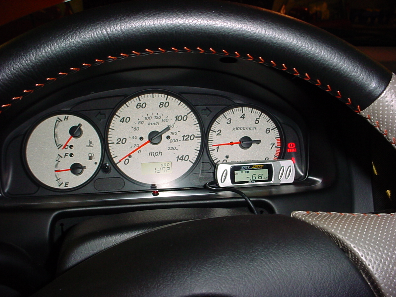
The Blitz DCTT 2 is a automatic turbo timer with a  built-in boost gauge.  It can
determine the amount of time to stay on based off of:
     a)	     The time that the ignition has been on
     b)	     The length of time you have been in boost above .1 hkPa
There is also a manual timer that can be set by your liking.
The boost gauge only reads in hkPa (hecto-kilo-Pascals), and the easiest way to convert it is:
     1.0	hkPa = 14.50 psi

You can also set a warning level, where an alarm will go off after a certain boost level.
Install:
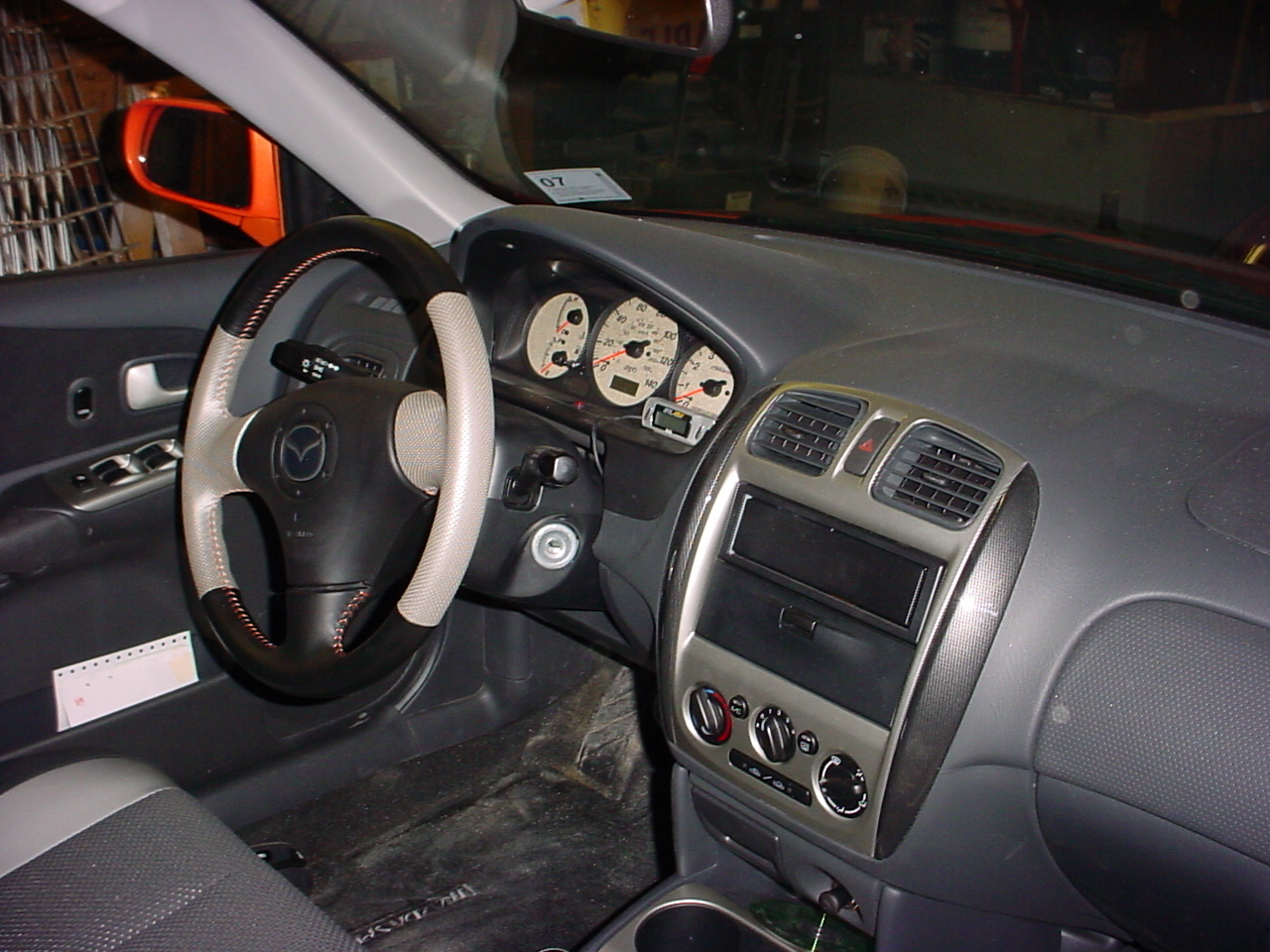
Start by removing the dash panel under the steering wheel:
It will just pop off with a little pulling.
Also remove the lower steering column cover (the upper portion can stay in place):
Remove the three screws from the bottom, and gently pry apart the upper and lower
portion. The light that illuminates the ignition pops out of its hole.
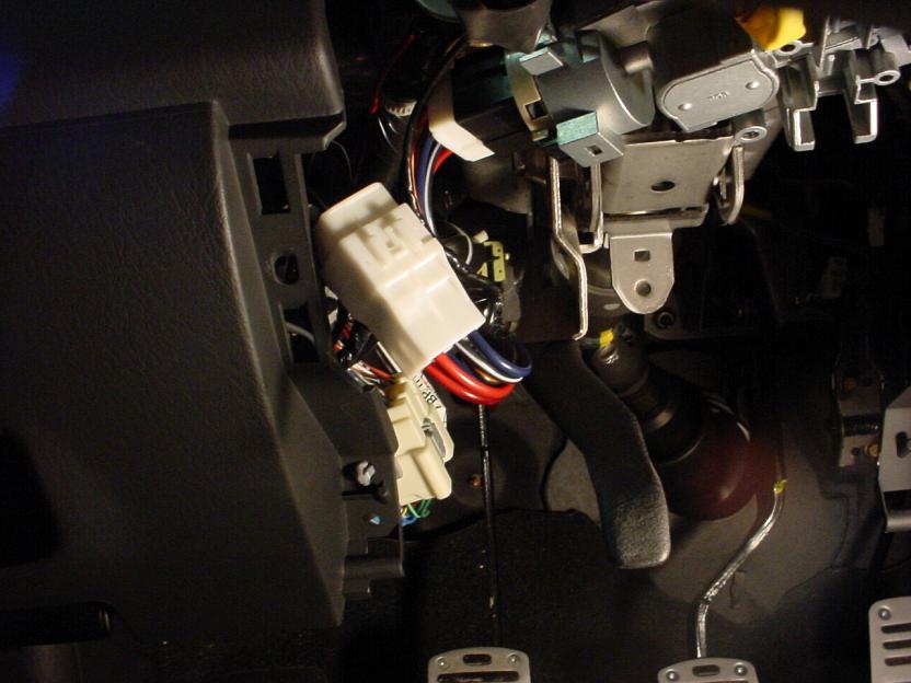
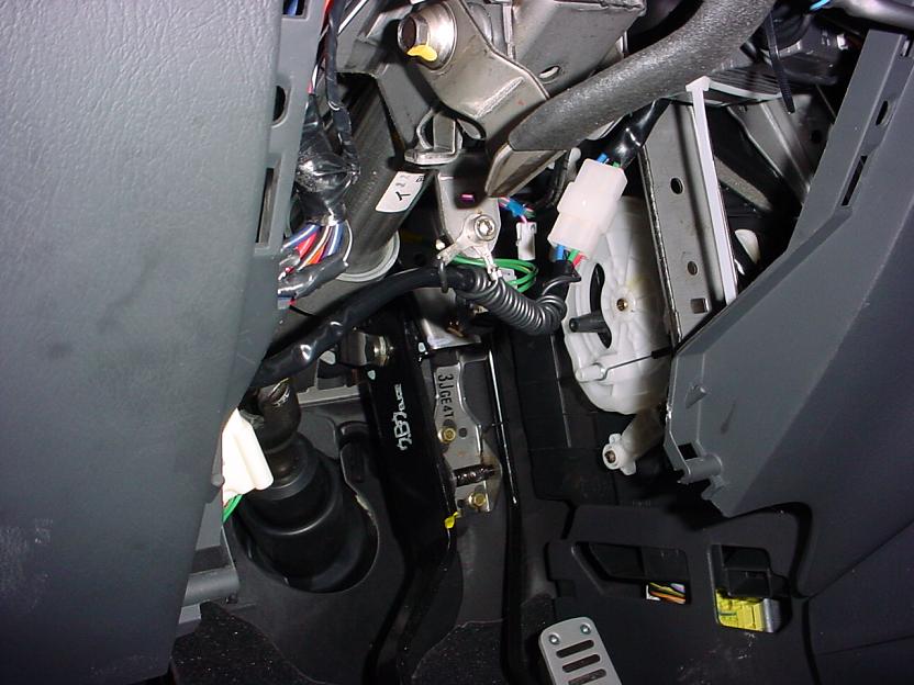
Now you have a clear view of the wiring under the steering column. the wires you will
use are connected to the ignition cylinder. If you start where you put the keys into
the ignition and follow it back, you will see the wiring harness you will tap in to.
The next step is to find a suitable location to mount the "brain" box for the timer.  When
doing this, keep in mind where you want to put your display unit, and make sure it will
reach.  I found an open space to the right of the steering column up against a bracket.
Make sure that the supplied wiring harness will reach the brain from where you will be
tapping into the ignition.
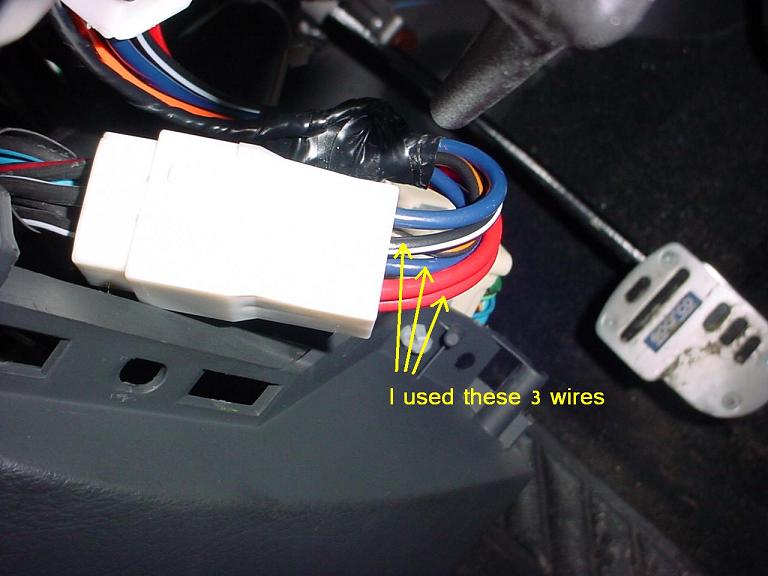
The three wires you will be tapping into are RED, BLUE and BLACK/WHITE. RED = constant 12V BLUE = Ignition Start 12V BLACK/WHITE = Accessory 12V You will find that there are 2 RED wires and 2 BLUE wires in the ignition wiring harness. Use a volt meter or a air-bag friendly test wire to determine which wires to use. Using a volt meter, I found no difference between the two RED wires. I did find a difference between the two BLUE wires one of them does not supply the 12V when in the start position. If you look at the end of the harness/plug with the 2 RED wires on top, I used the RED wire and BLUE wire that are one above the other, and I used the BLACK/WHITE wire that is next to the blue wire (NOTE: there is a BLACK/YELLOW wire next to a BLUE wire I did not use either of those).
Now you have to tap into the wires. Use your method of choice, but be sure that the connection is secure. I had a friend come down and he soldered the harness to the wires for me, and then wrapped the connections in electrical tape. This might be a good time to see if everythign got wired correctly...so, plug in the display and turn on the car. The display should turn on. Any smoke coming from under the dash?...I hope not. If everything seems ok, then continue. The next thing I did was determine where to tap into the vacuum lines to run the line for the boost gauge. I found a vacuum hose (approx. 3) coming off the top/center of the intake manifold close to the firewall.
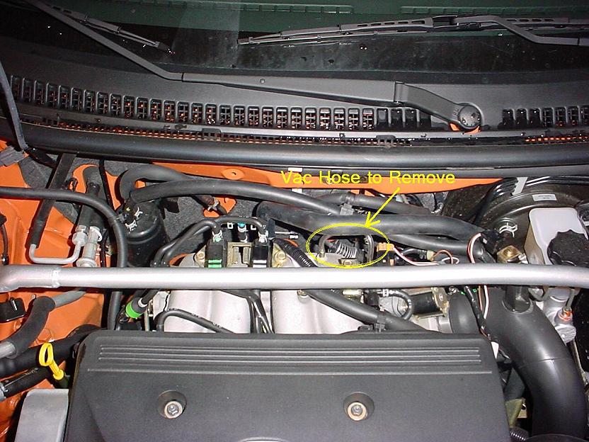
I removed that hose and saved it to replace if I ever needed to take my car in for warranty work. I then cut a length of vacuum hose the same length and cut it in half and put the T connection for the boost gauge tubing line in and reconnected that hose to the intake manifold.
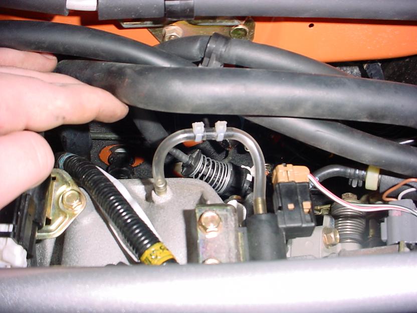
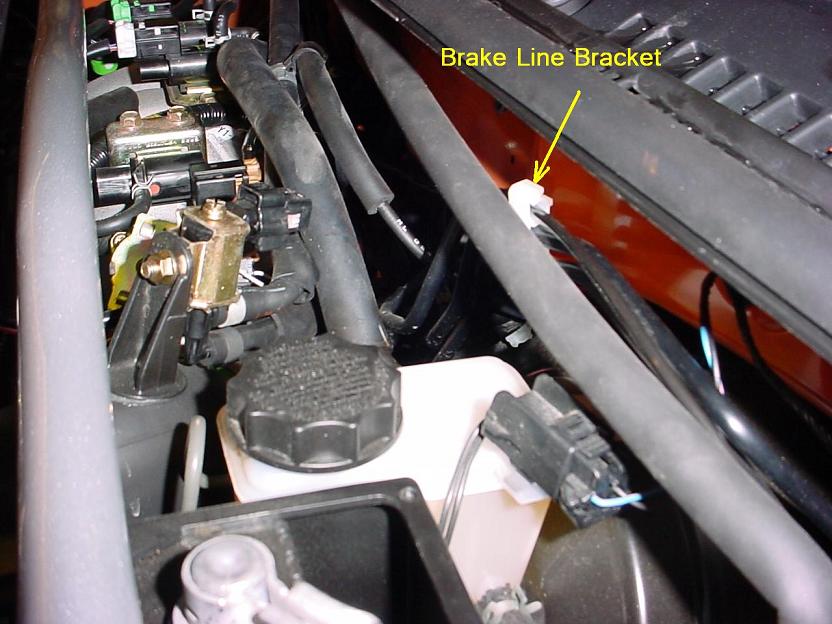
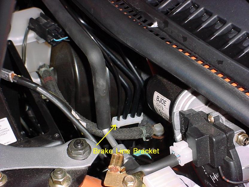
Now you have to run the boost gauge tubing line through the firewall.  A convenient
place is at a rubber grommet under the windshield washer motor that currently has wires
running through it.  I poked a hole in it and fed the boost gauge tubing line through.
Then I routed the boost gauge tubing from the firewall to the vacuum line using the
brackets that the brake lines go through.
Under the dash I pulled the excess tubing through, connected it to the turbo timer and coiled it up to use again if I decided to move the turbo timer later. The next thing to do is install the e-brake release shut-off wire. If you pull on the surrounding plastic around the e-brake handle, that piece will come out and you can have access to the wire. I unclipped the wire from its harness to have a little more room to work with and connected the tap supplied with the timer to it. Then I routed the wire back through the center console and up under the dash and connected it to the turbo timer. The last thing to do is set up the display where you want it and plug it into the "brain". Now you can reassemble everything and you should have a working turbo timer.